Principles for Selecting and Designing Manifolds
May 29, 2026
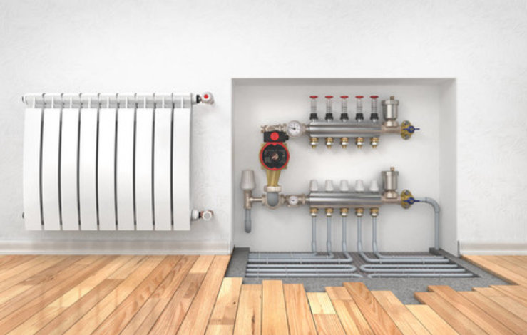
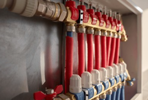
In projects utilizing centralized cooling and heating systems, to facilitate flexible and convenient flow distribution and regulation across individual HVAC zones, a manifold and a collector are often installed on the supply and return main pipes, respectively. The supply and return pipes for each HVAC zone are then connected to the manifold and collector, respectively. This configuration makes installation and maintenance operations on the supply and return pipes of each zone extremely convenient. Manifolds and return manifolds are essentially sections of large-diameter piping with several pipe fittings of different diameters welded onto them according to design requirements.
The principle for determining the pipe diameter of the manifold and collector is to maintain a flow velocity of approximately 0.5–0.8 [m/s] when water passes through. For example: If six supply pipes with a nominal diameter of Dg80 are to be connected from the manifold, and the design flow velocity for these supply pipes is 2.0 [m/s], what should be the appropriate diameter for the manifold? First, consult the manufacturer’s selection table to determine that the inner diameter of a Dg80 water and gas supply steel pipe is 80.5 [mm]. Calculating its cross-sectional area yields 51.9 [cm²]. Thus, the total flow cross-sectional area for six Dg80 pipes is 311.4 [cm²]. If the flow velocity within the manifold is set to 0.8 [m/s], the flow cross-sectional area of the manifold is 311.4 × (2.0 × 0.8) = 788.5 [cm²]. Therefore, the inner diameter of the manifold can be calculated as 315 [mm]. Referring to the specifications for steel pipes commonly used in air conditioning water systems in China, it can be concluded that selecting D325*8 seamless steel pipe is appropriate. Since the inner diameter of D325*8 seamless steel pipe is 309 [mm], the actual flow velocity of water inside the pipe is slightly greater than 0.8.
Other Considerations
A pipe can be used to directly connect the header and the manifold, with a valve installed in between. However, if the load on the user side decreases, the fan coil water supply solenoid valve will close, reducing the water flow rate. reducing water flow through the unit’s evaporator. If flow decreases, it inevitably leads to uneven flow velocity, particularly at transition points (such as end caps), where flow is more likely to slow down or even stagnate into “dead water.” Since the evaporation temperature is extremely low, low-velocity water or “dead water” is highly prone to freezing during the continuous cooling process in the evaporator, which can damage the chiller unit. The solution is to promptly open the valve to direct water from the manifold to the collector, ensuring uniform flow into the evaporator. However, this method is clearly cumbersome and impractical. Installing a differential pressure bypass valve can provide automatic control.
The operating principle of the differential pressure bypass valve is as follows: When the system is in its design state and all equipment is operating at full load, the valve is fully closed (no bypass flow). At this point, the pressure difference across the differential pressure controller (also known as the supply and return pressure difference on the user side) is the controller’s set differential pressure value. When the terminal load decreases, the two-way valves at the terminals close partially, causing the supply-return pressure differential to rise and exceed the set value. Under the action of the differential pressure controller, the bypass valve automatically opens. Since the bypass valve is connected in parallel with the user-side water system, its increased opening reduces the supply-return pressure differential until it reaches P0, at which point it stops. Part of the water flows through the bypass valve directly into the return pipe, mixes with the return water from the user side, and enters the pump and chiller. Thus, the water flow rate through the chiller remains unchanged.